Radome Specifications
Proper Radome Sizing
We offer many radomes that have a spherical shape with a truncation or height usually between 80% and 90% of the radome’s diameter. Radome diameter and truncation are primarily driven by antenna size and type. Although the exact radome size is determined by the specific antenna, some basic assumptions can be made to aid in obtaining a rough radome size. For preliminary design estimates, the following assumptions may be used.
Mounting Options antenna – equal to 2.3 times the reflector diameter
Prime Focus Feed Antenna
An on axis type antenna is a parabolic or nearly parabolic shape with a focal length verses antenna diameter (f/D) usually in the range of 0.4. Other features
- Cassegrain or Gregorian fed parabolic dish antenna
- Pedestal mounted collocated elevation and azimuth axis
- Antenna axis located in the geometric center of the radome
Offset Feed Antenna
An offset feed type antenna is a smaller segment of a parabolic dish with a much greater focal length than a similar sized prime focus antenna. For this style of antenna, use of a radome diameter equal to 2.3 times the reflector diameter is necessary.
These sizing assumptions have been shown to provide a realistic estimate for a suitable sized radome that will provide the following:
- Unrestricted range of motion for the antenna
- Clearance at zero degrees antenna elevation from reflector edge to ground
- Clearance for cabling and maintenance activities
Truncation
Truncation is the height of the radome measured from the base mounting surface to zenith and is expressed as a percentage of the radome diameter. IT RCS offers a variety of truncations ranging from less than 60% to approximately 90% to aid in matching user requirements
On Axis Example

Other antenna types such as dish systems that have separate elevation and azimuth axis positions and phased-array systems should be evaluated and placed within the radome to minimize system performance degradation which will sometimes use an offset truncation. As a general rule, a truncation equal to or less than 80% is commonly used for this application.
Although a useful tool for general estimating, no general guideline can cover all possible radome configurations. IT RCS strongly recommends our customers provide dimensional information on the specific antenna system for assistance in selecting a properly sized radome. IT RCS can also help when there is more than one antenna under the radome. The shape can be optimized for multiple antenna systems and the degree that the radome affects each enclosed system should be evaluated if this is the case.
In instances where the antenna is fixed in position or has a limited range of movement radome size can usually be decreased.
Antenna dimensional information most useful in correctly sizing a radome includes:
- Dish diameter
- Swing radius
- Height from ground to elevation and axis locations
- Relationship between elevation and azimuth axis
- Manufacturer model number
Composite Radome Sizes
Infinite Technologies’ radomes are currently available in sizes ranging from 3.1m (10ft) to 30m (98.4 ft) for ground-mounted radomes. Typical truncation for terrestrial radomes ranges from 50-90%. Radome height or truncation is easily adjusted for each model, this allows for optimal fit of the antenna within the radome without increased costs for customized tooling.
Our maritime radome sizes range from 1.4m (4.5 ft) to 2.5m (8.2 ft).
We can, and often do, provide other sizes and shapes for both land and ship radomes upon request. Since we have in-house tooling capabilities, we are able to minimize tooling and development costs for our customers.
Land-based


Maritime


Mechanical & Environmental Analysis
At IT RCS, we prioritize the unwavering structural integrity of our radomes. Our thorough analysis adheres to widely recognized engineering standards for buildings and various structures, ensuring compliance with mechanical and environmental requirements. To ascertain material properties, we empirically generate data from test coupons manufactured using the same materials and processes employed in the production environment. Additionally, we meticulously assess unique wind conditions in mountainous terrain, gorges, ocean promontories, and special wind regions, whenever necessary, to account for any unusual factors.
Standard Configuration for All ITI Radomes
- Wind speed of 155mph [250km/hr]
- Snow or ice load of 50lb/sqft [235-kg/m2]
- Factor of safety rating of 2.0 for radomes 22ft [6,7m] and larger, and 3.0 for smaller units
We evaluate each radome to ensure the customer’s specific requirements are met or exceeded. To achieve this, we offer a diverse range of radome models designed to withstand higher wind speeds, heavier snow and ice loads, and other atypical environmental conditions. Our configurations consistently adhere to self-imposed structural safety factors, ensuring compliance and reliability.
While basic wind speed is important, we recognize that other environmental factors significantly influence structural requirements. Therefore, all new radome configurations undergo Finite Element (FE) analysis. This analysis enables us to accurately determine the structural loads specific to the operating environment of the radome. By considering these factors, we ensure a structurally viable and durable design for optimal performance.
Site Variables
- Mounting configuration – ground or elevated (tower, building, etc)
- Basic wind speed and directionality
- Gust effect factors
- Importance factor – hurricane and non-hurricane locations
- Terrain exposure – vegetation
- Topographic factors – mountains, gorges

Snow and Ice Loading
- Balanced loading
- Unbalanced loading
- Exposure factor
- Thermal factor
- Importance factor
Engineered for Strength, reliability, and lasting performance
Electromagnetic
Radomes are built using a variety of materials, they have varying support structures, and sandwich radome configurations can have many combinations or ply schedules that build up a panel. Also, many of the practical materials used in radome production have varying properties at different frequencies. The primary effect a radome has on electromagnetics or RF performance is a reduction or attenuation of the signal. In general, the radome can also change the noise level seen by the system by changing the physical temperature of the electrical systems and by the attenuation effects.
From application to application, specific RF parameters are critical to system operation. In some applications, any affect to the sidelobes can be critical whereas in other applications affecting the sidelobes is not as critical. Distortion of the phase of the signal, or distortion of the radiation pattern in some applications is important. Thus, a best practice when examining a new application is to evaluate the critical system specifications and to select the correct type of radome configuration, size, and structure to meet the requirements for that system. For example, in a spherical radome, it is advantageous to position the center of the system antenna at the center of the spherical surface, which requires building radomes with different truncations to accommodate different antenna heights.
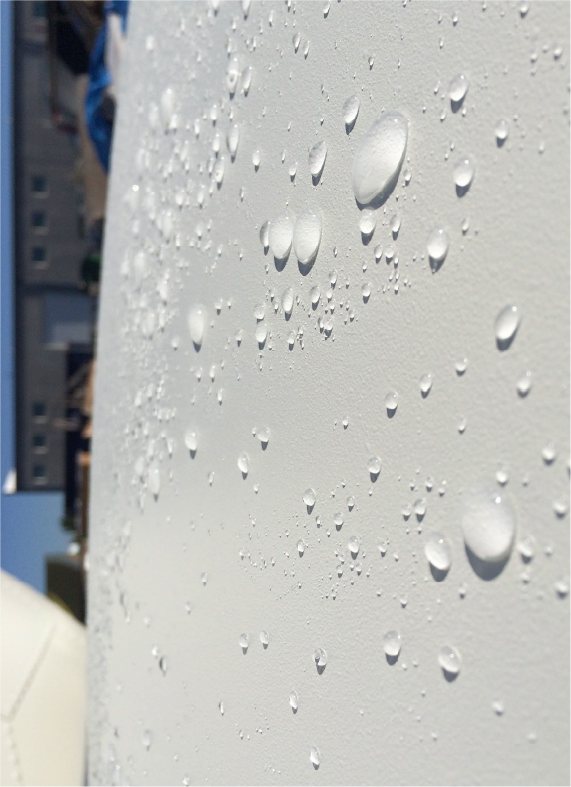
Hydrophobicity
Hydrophobic surfaces allow for water to bead and run off the radome surface rather than sheet and create a thin film of water which would have a negative effect on RF transmission. A hydrophobic surface allows the system to operate in heavy rain conditions with less effect on performance compared to a non-hydrophobic surface.
Our radomes are fabricated using a UV-stabilized hydrophobic coating that is integrated into the panel during lamination unlike paint which is applied after the lamination process. Integrating the surface coat during lamination creates a strong chemical bond between the coating and the panel resulting in a long-lasting, durable finish that requires minimal maintenance.
Post-applied super-hydrophobic coatings with contact angles exceeding 120 degrees are available; however, these coatings are not as durable and will likely require re-coating the radome every four to seven years. The coatings utilized by IT RCS can be applied in the field without requiring disassembly of the radome.
Mounting Options
Radomes can be mounted in many different ways depending on the mission of the end user and the environment of the installation site. While some of the common options are shown below, we have seen numerous other possibilities and can offer our expertise to help the user create a successful radome mounting outcome.

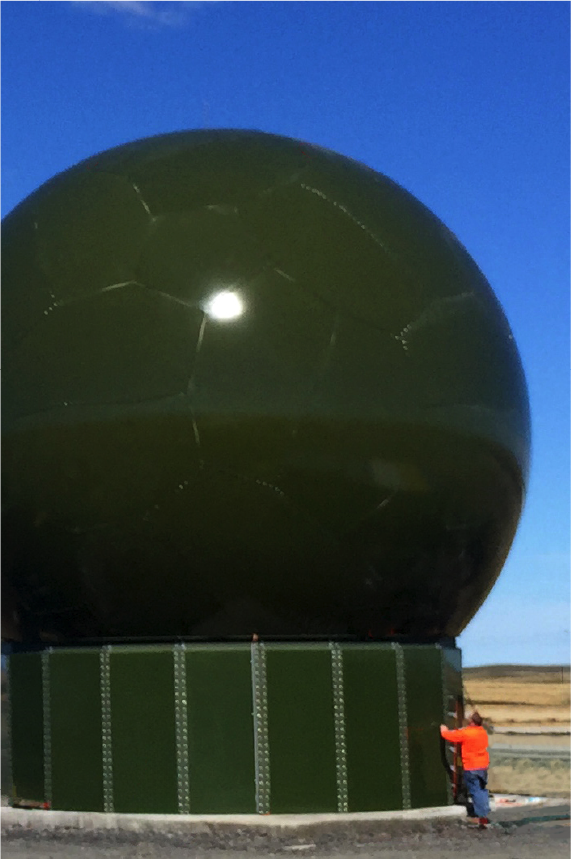
Radome Relocatable Ring Walls
IT RCS has developed solutions for rapid assembly of relocatable ring walls. The structure consists of standard steel shapes and a composite filler panel situated between the structural members. The ring walls are configured to support our sandwich wall radomes in areas subject to wind loads up to 190 mph [305km/h].
The steel portion of the ring wall is finished with a durable powder coat finish with a wide variety of color options, adhering to FED-STD-595 or RAL colors. The fiberglass filler panels are also finished with a durable gel-coat finish, which provides excellent color match options between the radome and the ring wall.
A personnel door can be incorporated into the Relocatable Ring Walls assembly by means of a special panel that replaces a standard wall segment, it is a direct bolt-in item that does not require modification and is flush with the top of the concrete mounting surface.
Wall geometry consists of faceted segments constructed from MC channel and W beams which are bolted together at the factory. The wall segments are secured to the foundation by means of anchor bolts embedded into a flat concrete foundation. The wall is a modular, transportable structure allowing it to be disassembled for transportation and erection in a new location simply by unbolting the segments, thus alleviating the need for additional civil or structural requirements.
Radome Color Options
Our radomes are supplied with a white exterior finish as standard; however, colors conforming to recognized standards are available for our typical hydrophobic coating. White and light grey are available if the super-hydrophobic coating option is required. We recommend using light colors on your radome and avoiding selecting dark colors, as radome performance and longevity may be negatively affected.
We also offer multi-color options for airfield and other specific applications, including multi-color camouflage.
