Radio Frequency Analysis
ITI-RCS approaches each radome order with a thorough review of the customer requirements. After a review of the customer requirements, the level of analysis required for each order is determined. RF Analysis starts with modeling the material properties and the physical dimensions of the proposed materials to estimate the effects of the radome on the system’s performance. Most applications are a trade-off between mechanical properties and electromagnetic effects, requiring some level of optimization. To validate the design, ITI-RCS uses a number analysis tools including:
- Flat panel loss as a function of incident angle and the radome structure selected
- Radome-shaped panel loss estimates
- Simulated antenna Far Field Radiation pattern
- Simulated antenna Far Field Radiation pattern including seam effects
- Full-wave characterization of joint or other structural aspects
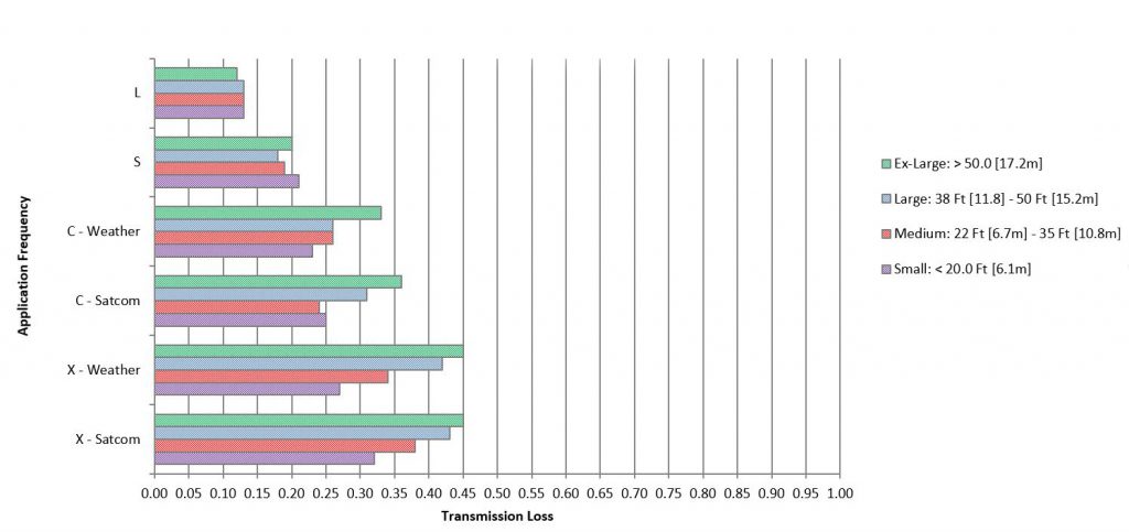
The outputs of these RF analyses allows system level requirements for boresight error, sidelobe degradation, total loss due to radome, scattering effects, and other system level requirements to be accurately estimated.
This chart is representative of typical radome performance; it does not capture every outcome for every scenario. For the best indication of how our radome will perform with your system, please contact us.
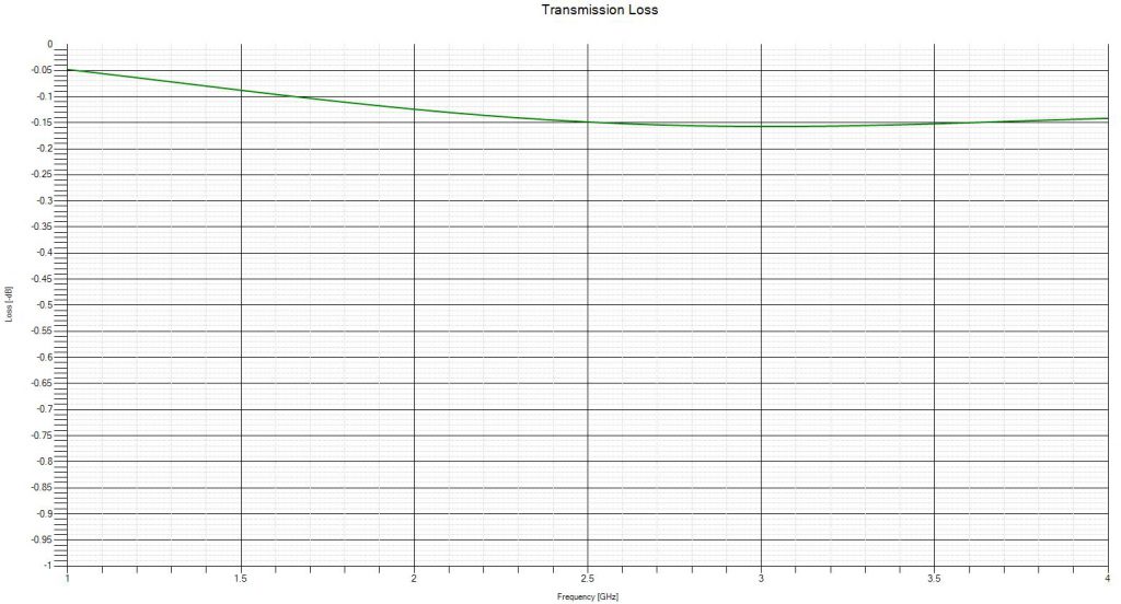
Air Traffic Management Application
We offer radome solutions capable of operating in common Air Traffic Management bands. The transmission loss prediction below is a sample of one solution developed for a specific ATM application with operating frequencies from 1-4 GHz. The transmission loss prediction takes into account radome diameter, dish diameter, as well as the radome panel construction both for the body and bolting seam.
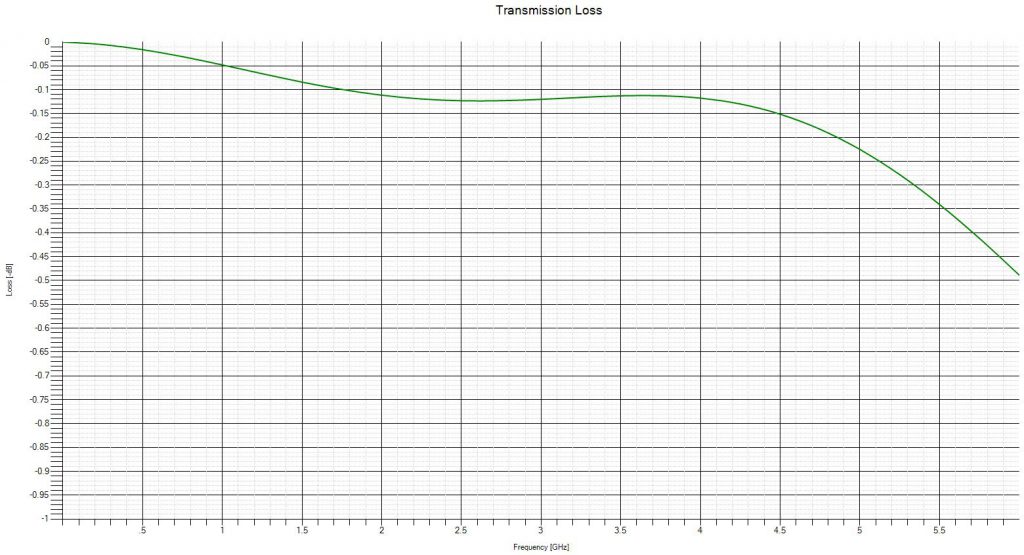
Telemetry Tracking & Control Application
The transmission loss estimate below shows an example of a radome that has been tuned for a specific application with the suggested operating frequencies of the customer. The transmission loss prediction takes into account radome diameter, dish diameter, as well as the radome panel construction both for the body and bolting seam.
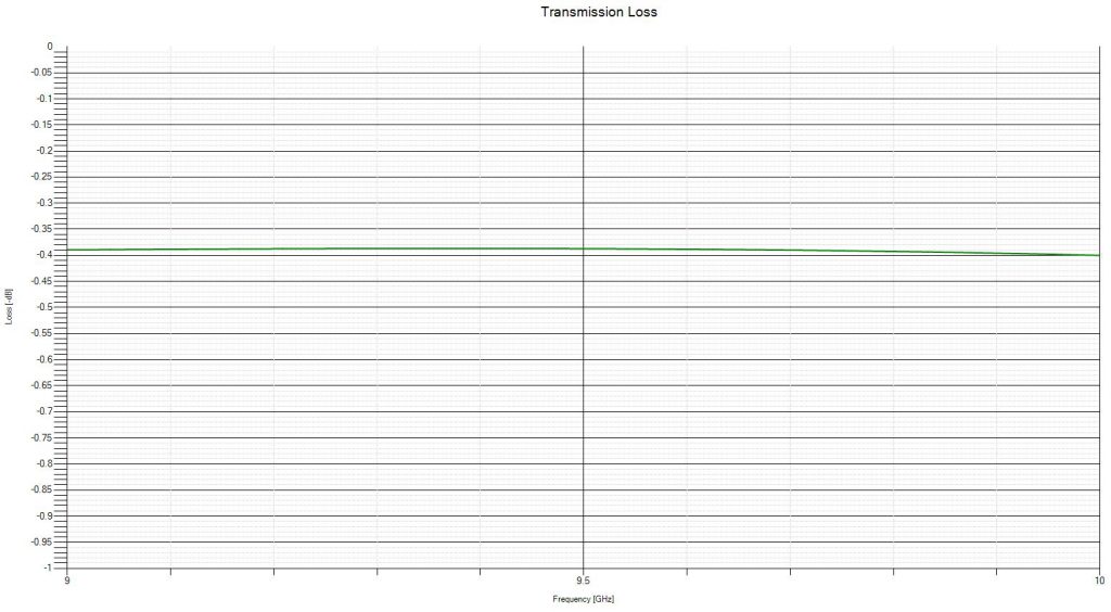
Weather Applications
This transmission loss prediction is a sample of one solution developed for a specific commercial weather radar. The transmission loss prediction takes into account radome diameter, dish diameter, as well as the radome panel construction both for the body and bolting seam.